Occlusal Limit - Axial milling:
藍線用於定義咬合面的停止面。
我們可以旋轉這條線,我們有較高的邊緣線和傾斜的基台。
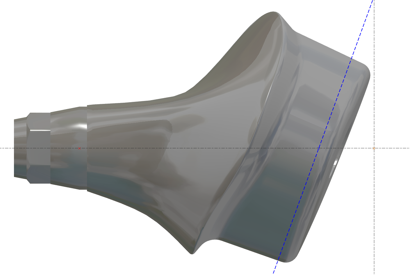
目標也是減少加工時間 - 藍線必須靠近該區域。
|
正確 
|
不正確 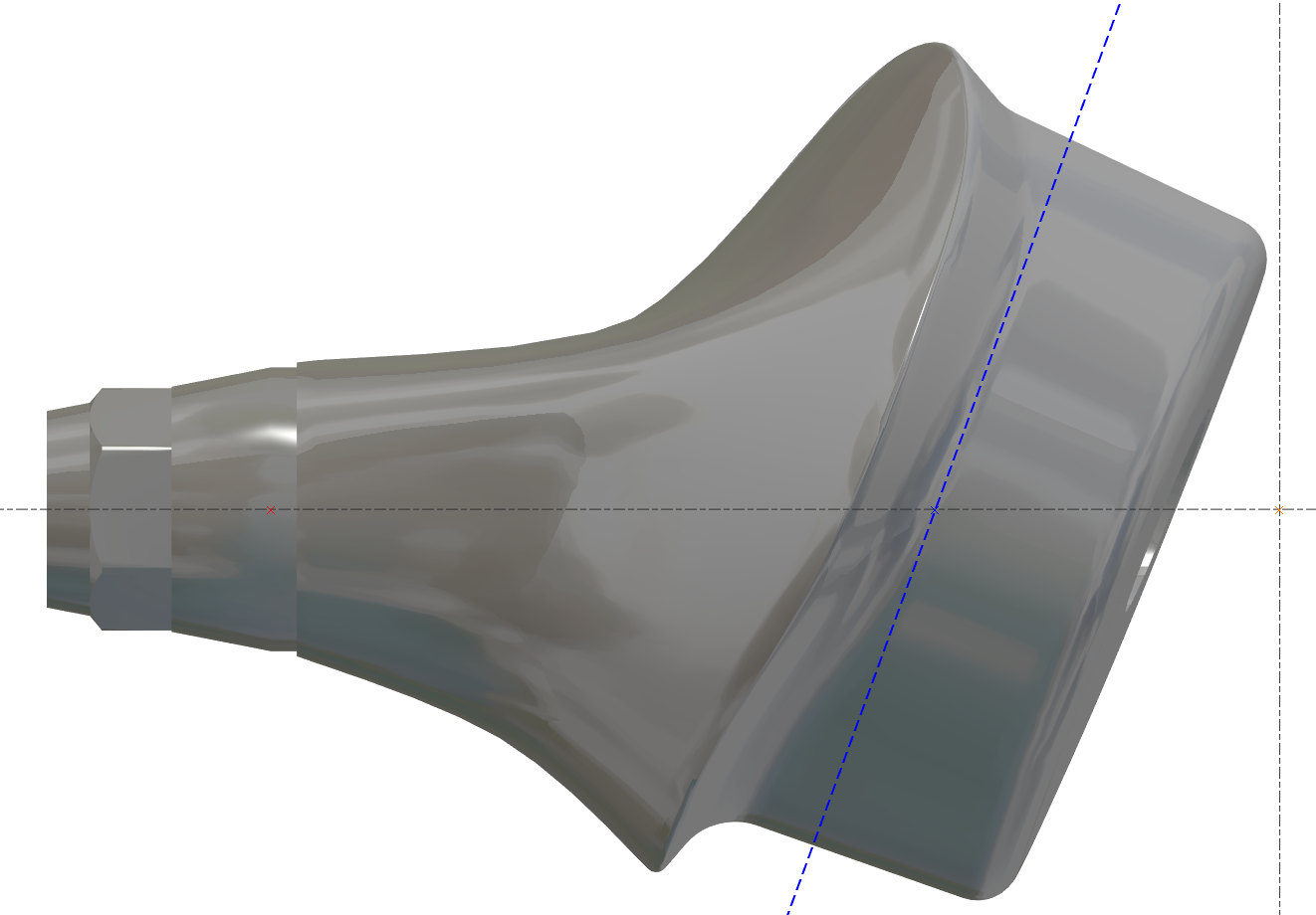
|
|---|
Change Stock Diameter - BUG inside the APP
機器內的值必須最大,然後我們可以更改它
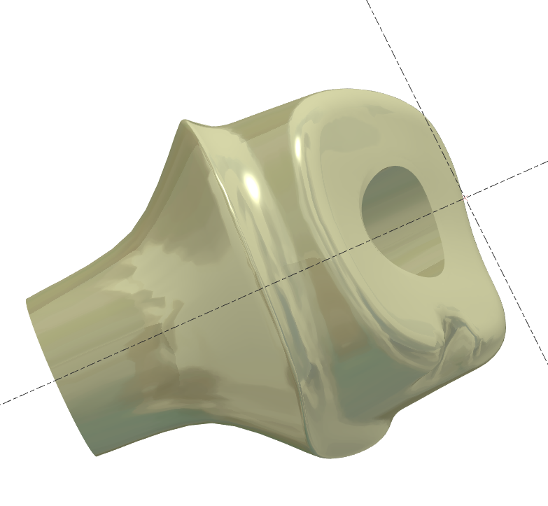
Abutment without Connectic
一些 STL 檔案沒有連接,但我們必須確保對齊正確。
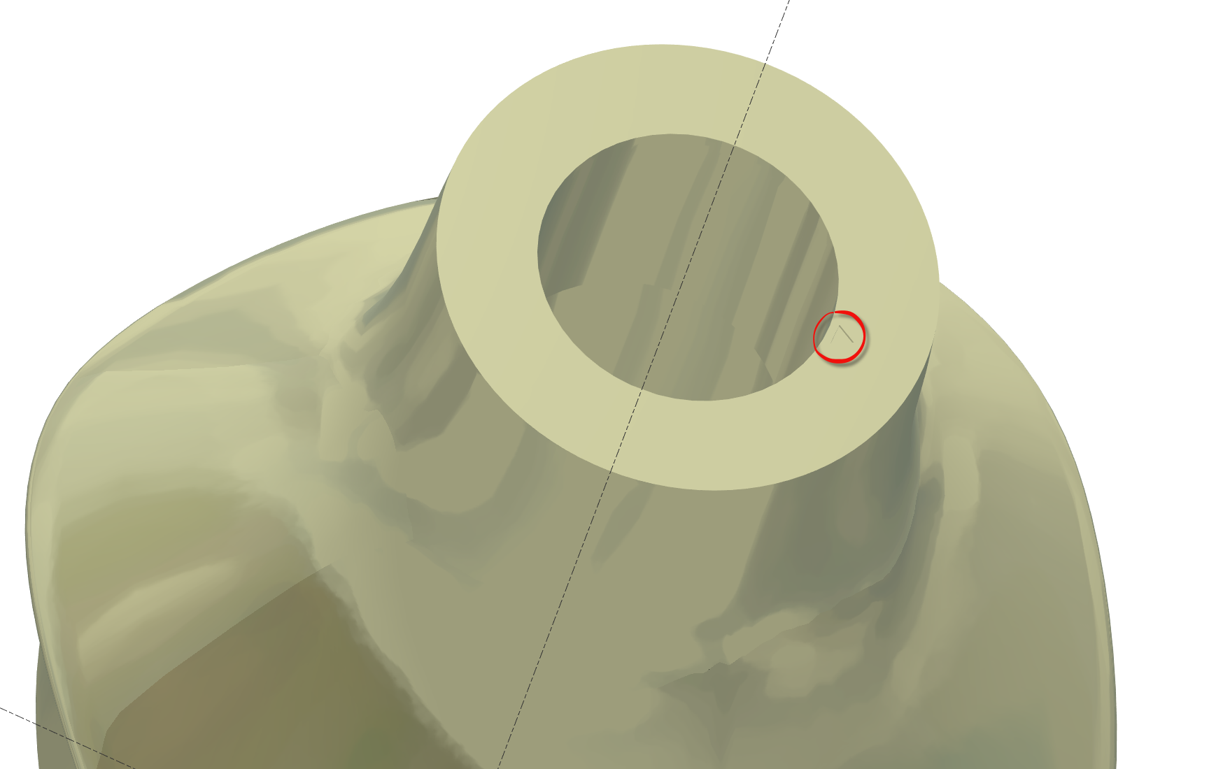
沒有連接的基台底部表面有“小三角形”指示參考位置
Have to have predifine view?
有些使用者想要預先定義的視圖,這取決於每個使用者。
我們可以有 3 個預定義的視圖。
使用者必須建立這些視圖。
將零件移動到正確的“預定義”視圖 N°1,然後按 CRTL+F2
將零件移動到正確的“預定義”視圖 N°2,然後按 CRTL+F3
將零件移動到正確的“預定義”視圖 N°3,然後按 CRTL+F4
然後要使用視圖,請按 F2 或 F3 或 F4
Rest material in the edge of side surface?
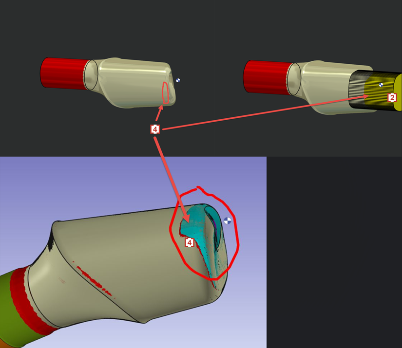
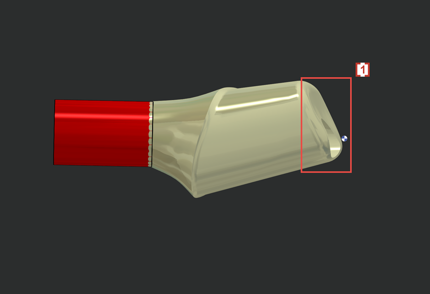
We don't want 4XS toolpath in this area of occlusion [1] .
4 軸刀具路徑會導致刀痕和不良的表面品質。
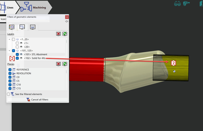
So we will create solid layer 102 [2] to prevent 4xs toolpath to contact and damage the occlusion surface on STL.
Now the 4xs toolpath [3] will not touch solid layer 102 [2] and so the occlusion surface [1] which is wrapped by layer 102 is protected.
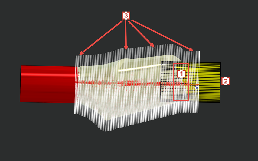
In some cases layer 102 will also cause some rest material in the edge of side surface [4] which is also wrapped by solid layer 102 [2] .