介紹

|
在輪廓的元素上定義錐度,它們可以是恆定的或演變的,我們可以在銳角上添加角。此功能在 EDM 和銑削中都可用。 |
筆記:
-
錐度不是幾何圖形,它們是分配給輪廓的資訊。
-
一旦完成這些資訊,您需要使用 EDM 錐度切割循環或錐度銑削循環來定義刀具路徑
-
或者您也可以使用 4 軸幾何圖形功能從錐度建立幾何圖形,以在 4 軸模式下進行加工(或在建立的實體上使用形狀循環)。
|
|
建立錐度
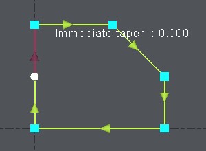
1. 定義輪廓:
起點是白色的,第一個元素是深紅色的。 |
|
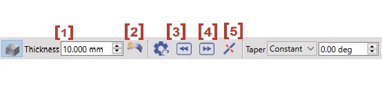
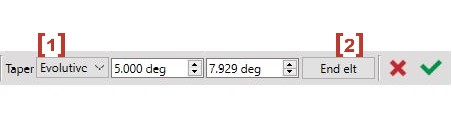
2. 對話框:
如果需要,您現在可以 逐個元素更改錐度值 :點擊要修改的元素,或使用按鈕 [3] and [4] to select the previous or the next element. |
|
|
關於錐度值的說明: 您也可以點擊 實體 的錐形面來 直接恢復值 的錐度。 首先點擊“吸管”圖標,然後點擊實體的面:該值會自動讀取並建立錐度。 |
|
3. 演進錐度:
|
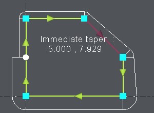
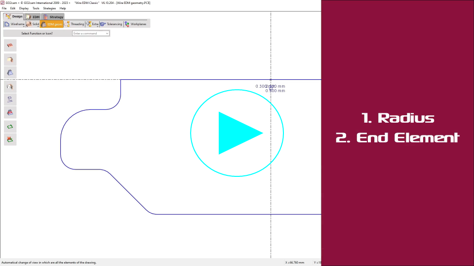
僅在一個元素上: Click on the element, choose [1] and type in the starting value and the ending value of the evolutive taper.
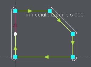
在多個元素上: Click on the first element, choose [1] and type in the starting value and the ending value of the evolutive taper. Then click on End elt [2] and click on the last element. 右側的示例顯示了 2 元素的演進錐度,從 5° 到 10° ,GO2cam 計算並顯示逐個元素的錐度,這裡第一個元素從 5° 到 7.929° 和下一個從 7.929° 到 10° . |
|
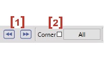
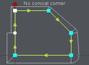
4. 錐形角落:
|
預設情況下,一旦定義了第一個錐度,GO2cam 會自動在銳角上生成錐形角。 當然,您可以更改它:
關於角落的注意事項: 您也可以在錐度切割循環的策略頁面中定義自動角落。 在這種情況下,它們是在整個輪廓上定義的。 這與您可以在錐度功能中在此處定義的角落無關。
|
|
5. 確認:
|
選擇 另一個輪廓 定義一個斜度,或 離開 功能(函數),再次點擊輪廓倒錐功能。 也可以離開功能(函數) Esc key 或在GO2cam中選擇另一個選單或功能(函數)。
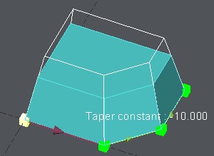
斜度直到你在加工編輯器中進行選擇後才會顯示。
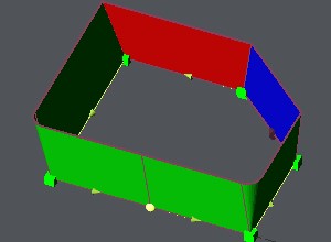
The 顯示 斜度方式 顯示素材在3D,並使用顏色約定:
在沖塊切割模式中,綠色和紅色在邏輯上反轉。 沖塊切割模式的選擇是在對話區用按鈕完成的。
你也有能力顯示著色的曲面在
透明
或不帶圖示:
|
|

|
|