演示

|
定义轮廓元素的锥度,它们可以是恒定的或演变的,我们可以在锐角上添加角。此功能在 EDM 和铣削中都可用。 |
笔记:
-
锥度不是几何体,它们是分配给轮廓的信息。
-
一旦这些信息完成,您需要使用 EDM 锥度切割循环或锥度铣削循环来定义刀具路径
-
或者您也可以使用 4 轴几何体功能从锥度创建几何体,以 4 轴模式进行加工(或对创建的实体使用形状循环)。
|
|
创建锥度
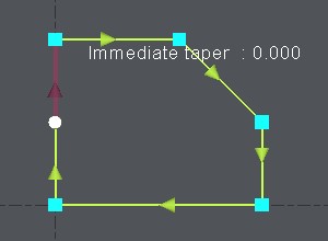
1. 定义轮廓:
起始点是白色的,第一个元素是深红色的。 |
|
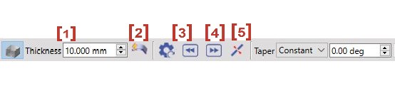
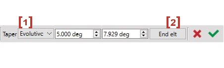
2. 对话框栏:
如果需要,您现在可以 逐个元素更改锥度值 :单击要修改的元素,或使用按钮 [3] and [4] to select the previous or the next element. |
|
|
关于锥度值的说明: 您也可以单击 实体 的锥形面来 直接恢复值 锥度。 首先单击“吸管”图标,然后单击实体的面:该值将自动读取并构建锥度。 |
|
3. 演变锥度:
|
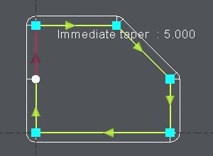
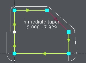
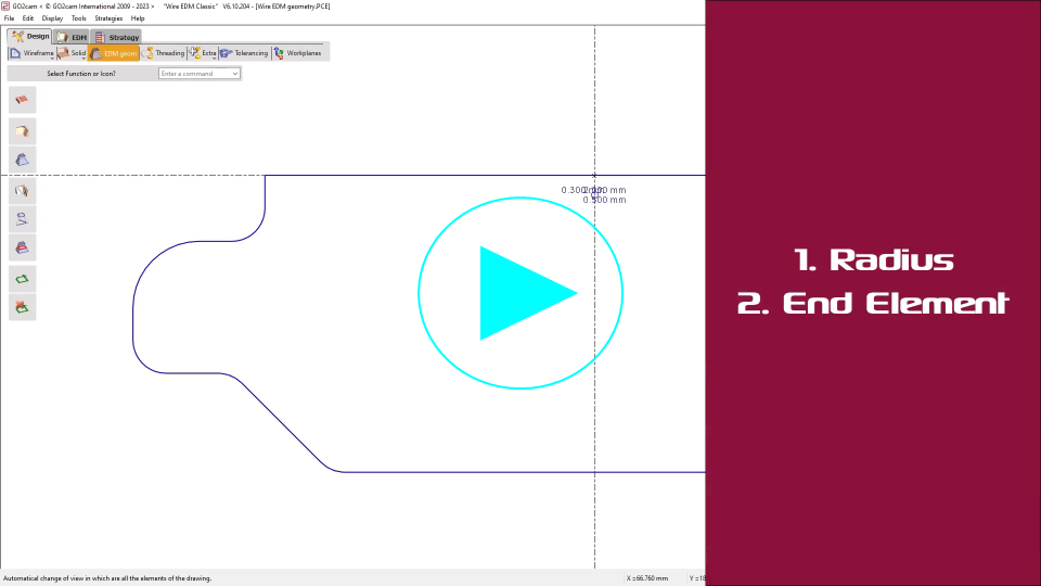
仅在一个元素上: Click on the element, choose [1] and type in the starting value and the ending value of the evolutive taper.
在各种元素上: Click on the first element, choose [1] and type in the starting value and the ending value of the evolutive taper. Then click on End elt [2] and click on the last element. 右侧的示例显示了 2 元素的演变锥度,从 5° 到 10° ,GO2cam 计算并显示逐个元素的锥度,这里第一个元素从 5° 到 7.929° ,下一个元素从 7.929° 到 10° . |
|
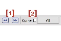
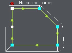
4. 圆锥角:
|
默认情况下,一旦定义了第一个锥度,GO2cam 会自动在锐角上生成圆锥角。您当然可以更改它:
关于角的说明: 您还可以在锥度切割循环的策略页面中定义自动角。在这种情况下,它们是在整个轮廓上定义的。这与您可以在锥度功能中在此处定义的角无关。
|
|
5. 确认:
|
选择 另一个轮廓 定义锥度,或 退出 该功能,再次单击轮廓锥度功能。 您也可以使用 Esc 键 退出该功能,或在 GO2cam 中选择另一个菜单或功能。
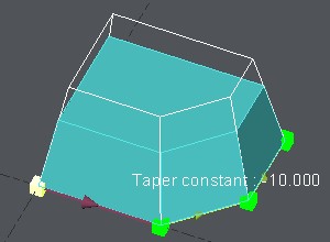
在加工编辑器中进行选择之前,不会显示锥度。
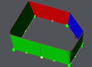
锥度的 显示 被大大修改。 可视化是 3D 的,并带有颜色约定:
在冲压模式下,绿色和红色在逻辑上是反转的。 模具/冲压模式的选择是在对话框区域中通过一个按钮完成的。
您还可以使用图标显示彩色面
透明度
或不显示:
|
|

|
|