循環 :鍵槽加工
可以加工任何類型的槽,以下是一些策略設置的樣本:
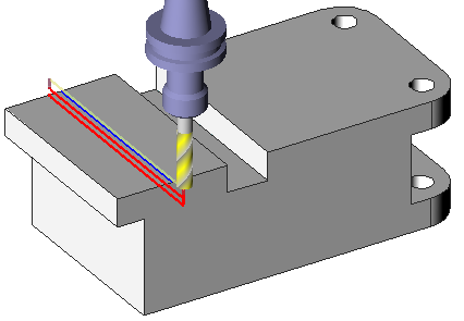
鍵槽加工中心 1 路徑
|
槽未在實體中設計,槽的中心有一個線段:
|
|
||
|
|
|
|
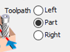
刀具路徑選項
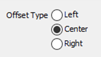
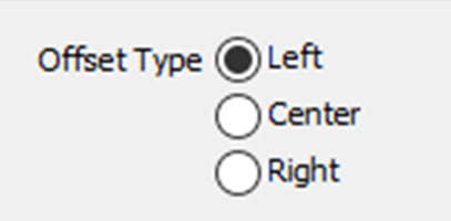
此設置僅在 中心 選項在 補正型式 欄位中被選中時啟動,提供以下選項的訪問。

雙向路徑設置為 否 . |
雙向設置為 是 且 連續刀路設置為 否 . |
雙向設置為 是 且 連續設置為 是 . |
鍵槽加工側邊
|
沒有中心,只有鍵槽的側邊。只需選擇線段並定義以下設置:
|
|
|
|

|
|
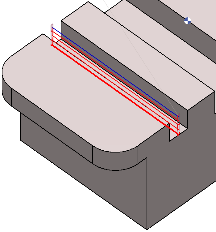
鍵槽加工 頂部和底部
|
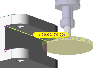
在這種情況下, 刀具路徑 和 補正型式 都已設置為左側。 輪廓的選擇直接在實體上完成。 也可以通過單擊實體來選擇高度(-20 和 -70)。 在策略中,選擇 兩個路徑顯示的引導層面 . |
|

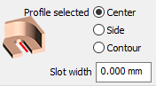
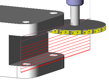
槽寬 = 0,因為我們直接選擇槽的底部。 |
|
|
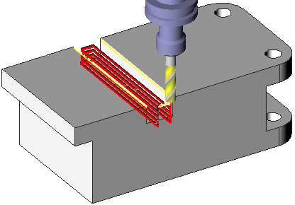
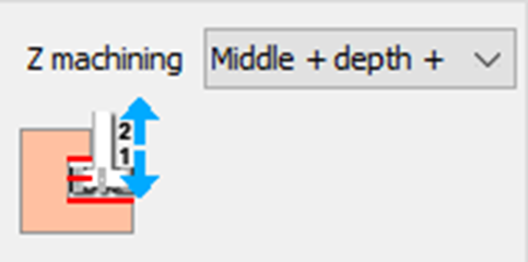
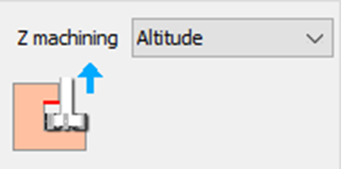
使用 Z向加工方式 設置為“中間 - 深度 + 高度”,定義流程:
|
|
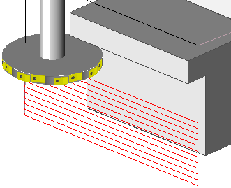
此行為可以在模擬中檢查。 |
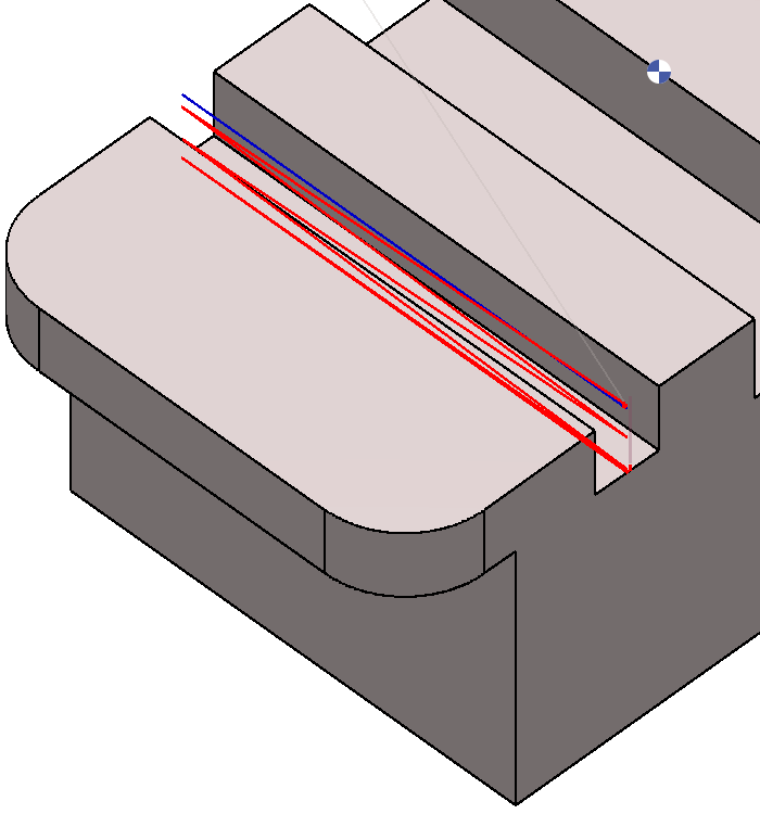
鍵槽加工 頂部
|
此案例與之前的範例非常相似:區別在於的管理 Z向加工方式 . 選擇高度,並通過直接點擊實體來定義頂部的高度。 |
|
|
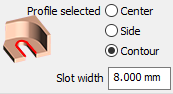
鍵槽加工 輪廓
|
此案例類似於鍵槽加工 中心 1 路徑。 然而,在這裡,可以直接通過選擇底部或輪廓線來完成選擇。 這允許製作一個槽,其寬度是刀具的側面 選擇“輪廓選擇方式: 輪廓 ”用於此策略。 |
|