Darstellung

|
Die Synchronisationspunkte werden auf 2 Profilen positioniert, um die Drahtbahn im 4-Achsen-Modus zu erzwingen. |
Es gibt 3 Schritte zum Positionieren von Synchronisationspunkten:
-
Definieren Sie die 2 Profile
-
Erstellen Sie eine Ergebnisliste, um zu überprüfen, ob Synchronisationspunkte benötigt werden
-
Definieren Sie Synchronisationspunkte im automatischen, manuellen oder kombinierten Modus
So definieren Sie Profile
1/ Define the profiles
Erstellen Sie ein Auswahlfeld oder klicken Sie nacheinander auf die 2 Profile.
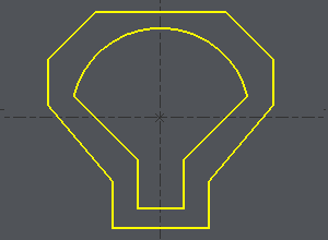
So definieren Sie den Startpunkt in der Mitte eines Elements, wie im Beispiel gezeigt:
-
Klicken Sie auf das Profil,
-
Klicken Sie auf das Startelement, bewegen Sie den Cursor entlang des Elements und klicken Sie dort, wo Sie den Start benötigen, oder wählen Sie den START oder die MITTE des Elements mit einem Klick auf die Schaltfläche: hier MITTE wählen
-
Klicken Sie auf das Endelement (im Beispiel dasselbe Element), bewegen Sie den Cursor entlang des Elements und klicken Sie dort, wo Sie das Ende benötigen, oder wählen Sie die MITTE oder das ENDE des Elements mit einem Klick auf die Schaltfläche: hier MITTE wählen.
|
|
2/ Outcome
-
Once the profiles are done, the dialog bar appears : Click on About the profile [1] . A message box give you the characteristics of the 2 profiles selected, number of elements, number of synchro points.
3/ To define the synchro points
|
|
Über das Profil |
|
|
Umkehrung der Richtung des ausgewählten Profils |
|
|
Hinzufügen von Synchronisationspunkten - Manuelle Erstellung von Synchronisationspunkten |
|
|
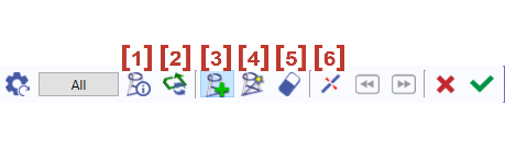
Automatische Erstellung von Synchronisationspunkten zwischen 2 Zonen. Klicken Sie auf die Schaltfläche ' Alle ' und die Erstellung erfolgt automatisch für die gesamten Profile. |
|
|
Löschen eines Synchronisationspunkts durch Anklicken. |
|
|
Schnitt eines Elements |
Klicken Sie auf das grüne Häkchen ' Anderes Profil ' um zu bestätigen oder einen Synchronisationspunkt auf 2 anderen Profilen zu erstellen.
Klicken Sie auf das rote Kreuz, um alle erstellten Synchronisationspunkte zu löschen.
Bei der Erstellung von Synchronisationspunkten können wir manuelle und automatische Erstellung kombinieren. Dies wird im zweiten Beispiel oben erläutert.
Automatische Methode
|
Click on [1] . There are 7 elements on a profile and 11 in the other one. It can be machined with the cycle 4 axes contour/contour but it is not optimized. If you want to optimize the toolpath, you have to set up synchro points. |
|
|
The synchro point can only be defined on existing points or elements extremities. You have to cut an element : click on [6] and then click on the arc, you can move the cursor all along the element, click on the screen when you want to cut. A circle (tangency) or a square (sharp angle) is displayed where you cut. |
Schnitt des Bogens mit dem weißen Cursor 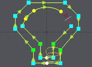
|
|
The number of elements is now the same on the 2 profiles : Click on [4] und klicken Sie dann auf ' Alle ', alle Endpunkte der 2 Profile werden paarweise verknüpft. |
Die Synchronisationspunkte werden automatisch erstellt 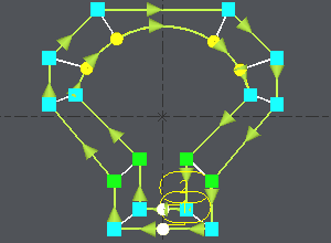
|
Manuelle und automatische Methoden kombiniert
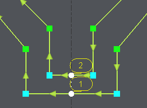
Nehmen wir ein identisches Beispiel, aber mit 2 weiteren Ecken. Hier müssen wir doppelte Synchronisationspunkte erstellen, und dies ist im automatischen Modus nicht möglich:
|
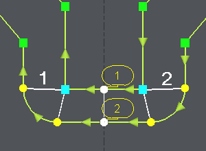
Click on [1] to have information about the 2 profiles. |
|
|
Click on [3] , click on the angle (blue square) and click on an extremity of the corner (yellow circle), click again on the angle (blue square), a message warns you about the creation of a double synchro point, click on OK and click on the other extremity of the corner (yellow circle). Wiederholen Sie die gleichen Vorgänge an der anderen Ecke. |
|
|
The synchro point can only be defined on existing points or elements extremities. You have to cut an element : click on [6] and then click on the arc, you can move the cursor all along the element, click on the screen when you want to cut. A circle (tangency) or a square (sharp angle) is displayed where you cut. |
|
|
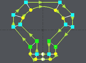
We want to create synchro points between the 2 corners already treated : click on [4] , klicken Sie auf die 2 bereits definierten Synchronisationspunkte ( 1 und 2 im Bild), um den zu bearbeitenden Bereich zu begrenzen, werden alle Endpunkte der 2 Profile paarweise verknüpft. |
Once the synchro points are set up, click on [1] to obtain information for the synchro points created , if the machining is possible you are told about it. Then you can go to the machining editor and choose the cycle 4 axes cnt/cnt.