概要

|
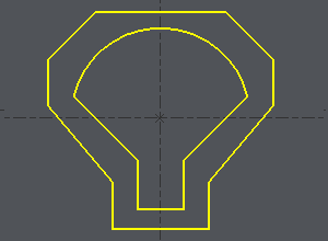
同期点は、4軸モードでワイヤパスを強制するために、加工する2つの輪郭上に配置されます。 |
同期点を配置するには、3つの手順があります。
-
2つの輪郭を定義する
-
同期点が必要かどうかを確認するためのアウトカムを作成する
-
自動、手動、または組み合わせモードで同期点を定義する
輪郭を定義するには
1/ Define the profiles
選択ボックスを使用するか、2つの輪郭を順番にクリックします。
例に示すように、要素の中央に開始点を定義するには:
-
輪郭をクリックし、
-
開始要素をクリックし、カーソルを要素に沿って移動して開始位置をクリックするか、ボタンをクリックして要素の開始または中央を選択します:ここでは中央を選択します
-
終了要素(例では同じ要素)をクリックし、カーソルを要素に沿って移動して終了位置をクリックするか、ボタンをクリックして要素の中央または終了を選択します:ここでは中央を選択します。
|
|
2/ Outcome
-
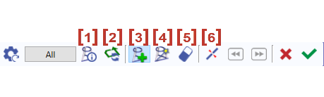
Once the profiles are done, the dialog bar appears : Click on About the profile [1] . A message box give you the characteristics of the 2 profiles selected, number of elements, number of synchro points.
3/ To define the synchro points
|
|
輪郭について |
|
|
選択した輪郭の方向の反転 |
|
|
同期点の手動作成 |
|
|
2つの領域間の同期点の自動作成。「 すべて 」ボタンをクリックすると、すべての輪郭で自動的に作成されます。 |
|
|
同期点をクリックして削除します。 |
|
|
要素の切断 |
緑色のチェックマーク「 他の輪郭 」をクリックして、確認するか、他の2つの輪郭に同期点を作成します。
赤いバツ印をクリックして、作成されたすべての同期点をキャンセルします。
同期点を作成する際には、手動作成と自動作成を組み合わせることができます。これは上記の2番目の例で説明されているとおりです。
自動方法
|
Click on [1] . There are 7 elements on a profile and 11 in the other one. It can be machined with the cycle 4 axes contour/contour but it is not optimized. If you want to optimize the toolpath, you have to set up synchro points. |
|
|
The synchro point can only be defined on existing points or elements extremities. You have to cut an element : click on [6] and then click on the arc, you can move the cursor all along the element, click on the screen when you want to cut. A circle (tangency) or a square (sharp angle) is displayed where you cut. |
白いカーソルで円弧を切断 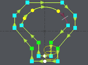
|
|
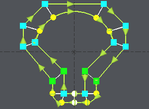
The number of elements is now the same on the 2 profiles : Click on [4] そして「 すべて 」をクリックすると、2つの輪郭の端点がすべて2つずつリンクされます。 |
同期点が自動的に作成されます 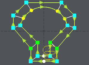
|
手動と自動の方法を組み合わせる
2つのコーナーを追加した、同じ例を考えてみましょう。ここでは、二重同期点を作成する必要があり、自動モードではこれは不可能です。
|
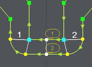
Click on [1] to have information about the 2 profiles. |
|
|
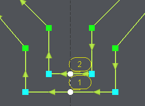
Click on [3] , click on the angle (blue square) and click on an extremity of the corner (yellow circle), click again on the angle (blue square), a message warns you about the creation of a double synchro point, click on OK and click on the other extremity of the corner (yellow circle). 他のコーナーでも同じ操作を繰り返します。 |
|
|
The synchro point can only be defined on existing points or elements extremities. You have to cut an element : click on [6] and then click on the arc, you can move the cursor all along the element, click on the screen when you want to cut. A circle (tangency) or a square (sharp angle) is displayed where you cut. |
|
|
We want to create synchro points between the 2 corners already treated : click on [4] ,既に定義されている2つの同期点(画像の 1 と 2 )をクリックして処理する領域を制限すると、2つの輪郭の端点がすべて2つずつリンクされます。 |
Once the synchro points are set up, click on [1] to obtain information for the synchro points created , if the machining is possible you are told about it. Then you can go to the machining editor and choose the cycle 4 axes cnt/cnt.